– By Rudmila Rahman, System Engineer (Muspana)
The current carrying capacity, commonly referred to as ampacity, is the maximum continuous electrical current that a conductor can carry under specified conditions without exceeding its permissible temperature limit. Correct ampacity calculation is essential to ensure electrical safety, thermal stability, energy efficiency, and compliance with electrical standards. Improper cable sizing may lead to insulation damage, excessive voltage drops, fire hazards, or premature system failure.

In today’s article, we explain the fundamental concept of cable ampacity, the key factors that influence it, and how standard-based calculations are applied in practical electrical design.
1.Definition of Ampacity
Ampacity is defined as the maximum current, in amperes (A), that a cable or conductor can safely carry continuously under normal operating conditions without causing excessive heating.
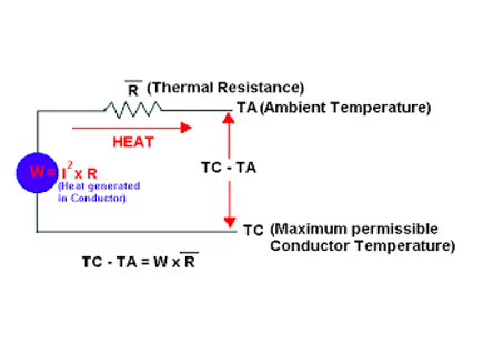
Mathematically, ampacity is governed by the balance between:
- Heat generated due to electrical resistance
- Heat dissipated to the surrounding environment

2. Importance of Ampacity Calculation
Accurate ampacity calculation is critical for:
- Preventing overheating and insulation degradation
- Avoiding fire and electrical hazards
- Ensuring reliable system performance
- Minimizing power losses
- Meeting regulatory and standard compliance requirements
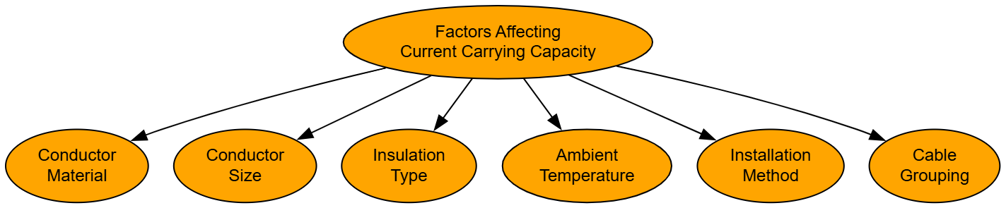
3. Factors Affecting Current Carrying Capacity
The ampacity of a cable depends on several interrelated factors:
3.1 Conductor Material
- Copper: Higher conductivity, higher ampacity
- Aluminum: Lower conductivity, requires larger cross-section for the same current
3.2 Conductor Size (Cross-Sectional Area)
Larger cross-sectional area → lower resistance → higher ampacity.
3.3 Insulation Type
Different insulation materials have different maximum allowable temperatures:
- PVC: typically 70°C
- XLPE: typically 90°C
- EPR: up to 90–105°C
Higher temperature-rated insulation allows higher ampacity.
3.4 Ambient Temperature
Higher ambient temperature reduces heat dissipation, lowering ampacity.
3.5 Installation Method
- In free air
- In conduit
- Buried underground
- In cable trays
Cables installed in confined spaces have reduced ampacity due to limited heat dissipation.
3.6 Grouping or Bundling of Cables
Multiple cables grouped together generate additional heat, requiring derating.
4. Basic Principle of Ampacity Calculation
The heat generated in a conductor is given by:
P=I2R
Where:
- P = Power loss (W)
- I = Current (A)
- R = Resistance (Ω)
Safe ampacity ensures that the conductor temperature remains below the insulation’s maximum rated temperature.
5.Standard-Based Ampacity Determination
In practice, ampacity is not calculated purely from equations. Instead, standard tables provided by electrical codes are used, such as:
- IEC 60364
- NEC (NFPA 70)
- IEEE standards
These tables already consider conductor material, insulation type, and installation method.
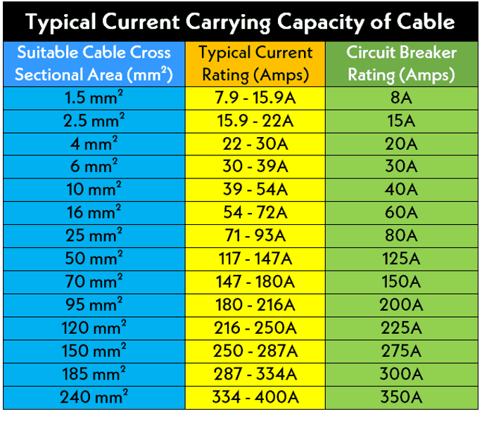
Example (IEC-based):
For a copper, XLPE-insulated, 3-core cable, installed in air or conduit:
|
Cable Size |
Standard Ampacity |
| 25 mm² |
≈ 100 A |
➡️ This 100 A is read directly from the standard table, assuming:
- Ambient temperature = 30°C
- Single circuit
- Standard installation method
6.Derating Factors
When actual conditions differ from standard conditions, correction (derating) factors must be applied.
6.1 Temperature Correction Factor
Icorrected=Irated×Ktemp
Example (IEC for XLPE cable, 90°C rated):
|
Ambient Temp (°C) |
Correction Factor |
|
30 |
1.00 |
| 35 |
0.96 |
|
40 |
0.91 |
| 45 |
0.87 |
| 50 |
0.82 |
6.2 Grouping Correction Factor
Ifinal=Icorrected×Kgroup
IEC / NEC Grouping (Bundling) Tables Example:
|
Number of Loaded Cables |
Grouping Factor |
|
1 |
1.00 |
|
2 |
0.85 |
| 3 |
0.80 |
|
4–6 |
0.70 |
Where:
- Ktemp = Ambient temperature correction factor
- Kgroup = Cable grouping correction factor
7.Example Calculation
Given:
- Copper cable, XLPE insulated
- Rated ampacity from table: 100 A
- Ambient temperature: 45°C
- Temperature correction factor: 0.87
- Grouping factor (3 cables): 0.8
Calculation:
Ifinal=100×0.87×0.8=69.6
Result:
The safe current carrying capacity is approximately 70 A.
8.Consequences of Incorrect Ampacity Selection
- Overheating and insulation failure
- Increased voltage drop
- Reduced cable lifespan
- Fire risk
- Non-compliance with electrical codes
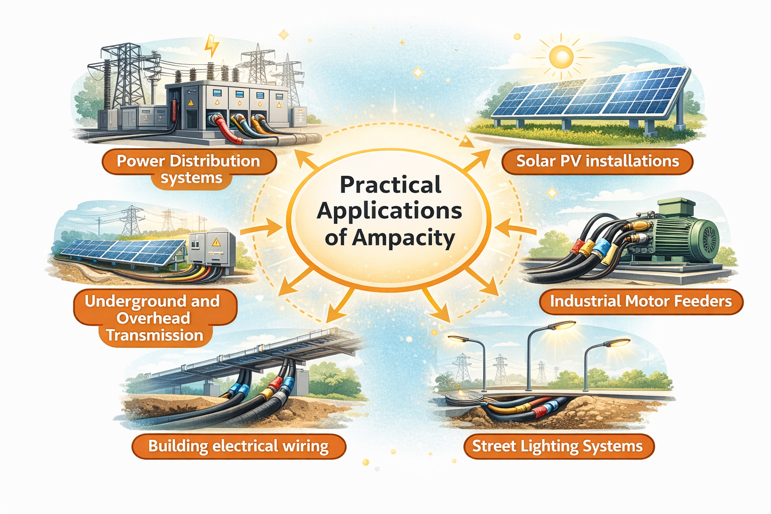
9.Practical Applications
Ampacity calculations are essential in:
- Power distribution systems
- Solar PV installations
- Industrial motor feeders
- Street lighting systems
- Building electrical wiring
- Underground and overhead transmission
Current carrying capacity (ampacity) calculation is a fundamental aspect of electrical system design. It ensures operational safety, system reliability, and regulatory compliance. While theoretical principles explain the heat-current relationship, practical ampacity determination relies on standard tables and correction factors to reflect real-world installation conditions. Proper understanding and application of ampacity principles are essential for all electrical engineers and technicians.