–By Md.Mahmudul Hasan Rifat, Deputy Manager (Muspana)
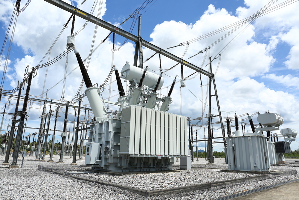
An electrical substation is a control hub of the power system. It receives electrical power, changes voltage levels, protects the network from faults, and routes electricity onward with precision. Serving as a vital link between generation, transmission, and distribution, substations ensure the safe, reliable, and efficient flow of electricity across the grid. From high-voltage transmission to low-voltage distribution, they play a crucial role in maintaining system stability and continuity of supply. This article provides a concise overview of electrical substations, covering their purpose, types, key components, voltage levels, layouts, and essential design and calculation considerations.
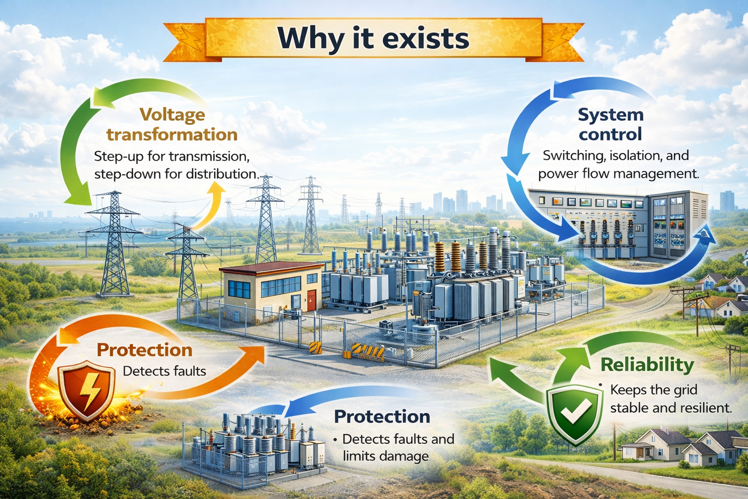
Why it exists
- Voltage transformation: Step-up for transmission, step-down for distribution.
- System control: Switching, isolation, and power flow management.
- Protection: Detects faults and limits damage.
- Reliability: Keeps the grid stable and resilient.
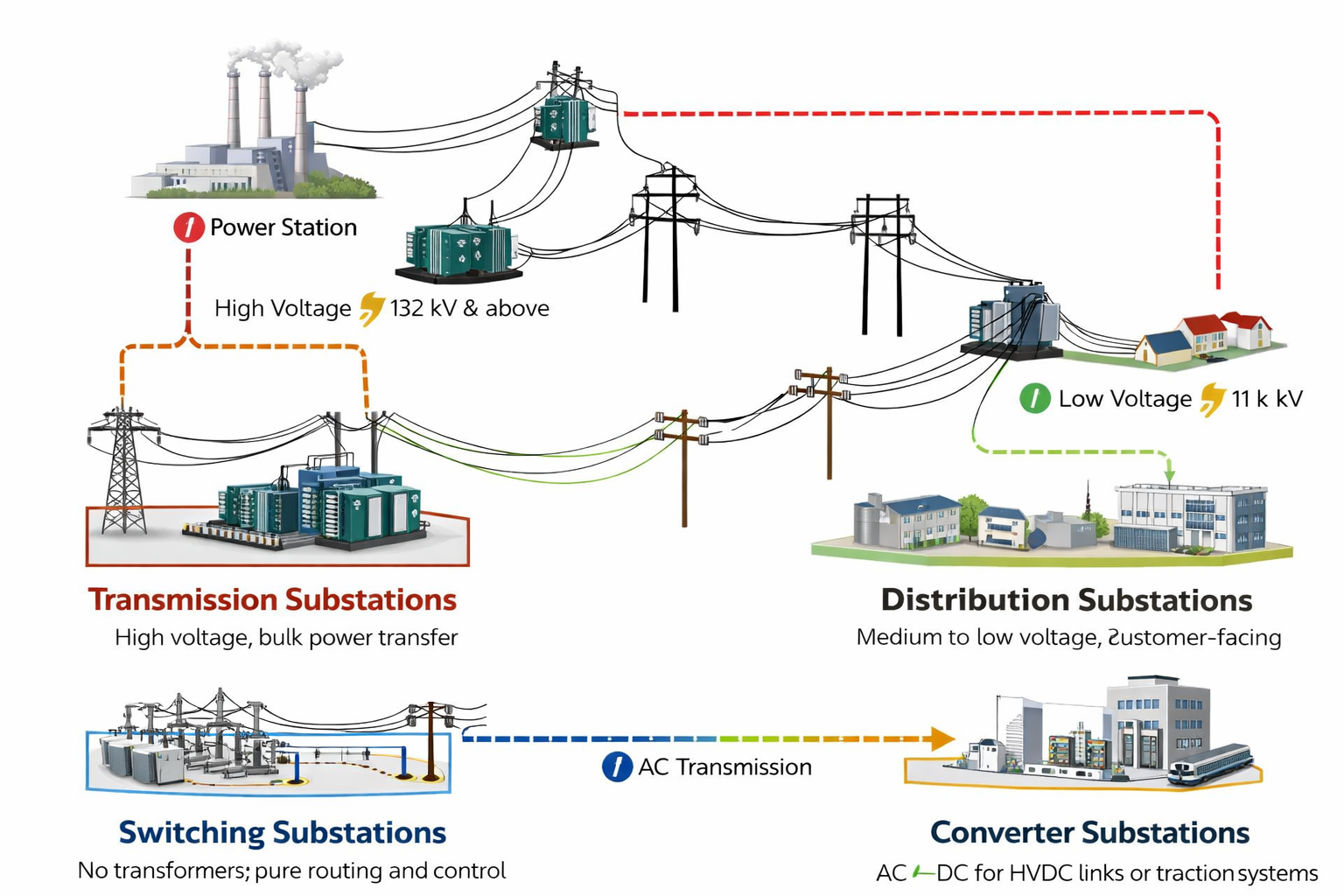
Main types
- Transmission substations: High voltage, bulk power transfer.
- Distribution substations: Medium to low voltage, customer-facing.
- Switching substations: No transformers; pure routing and control.
- Converter substations: AC↔DC for HVDC links or traction systems.
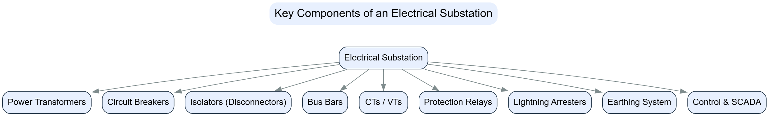
Key components
- Power transformers: Change voltage levels efficiently.
- Circuit breakers: Interrupt fault currents safely.
- Isolators (disconnections): Provide visible isolation for maintenance.
- Bus bars: Common connection points for incoming/outgoing circuits.
- Current & voltage transformers (CTs/VTs): Measurement and protection inputs.
- Protection relays: Decide when to trip—fast, selective, decisive.
- Lightning arresters: Shield equipment from surges.
- Earthing system: Safety backbone; controls touch and step voltage.
- Control & SCADA: Remote monitoring, automation, and alarms.
Voltage levels (typical)
- Transmission: 132 kV, 220 kV, 400 kV and above
- Sub-transmission: 33 kV, 66 kV
- Distribution: 11 kV, 0.4 kV
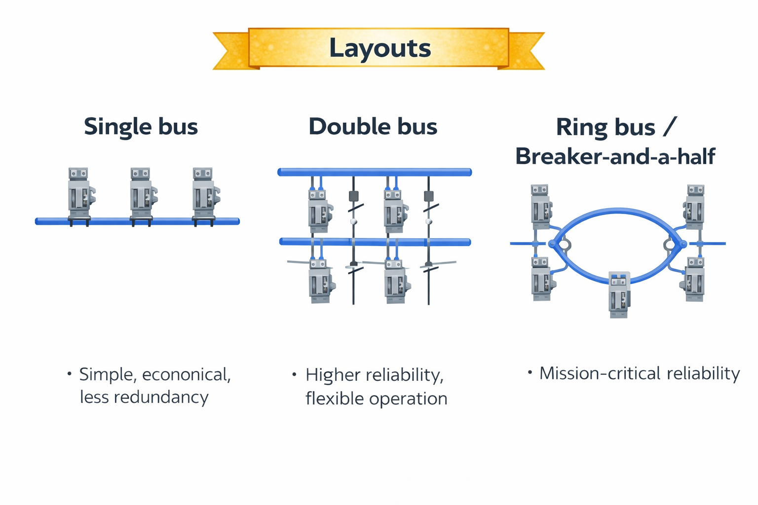
Layouts
- Single bus: Simple, economical, less redundancy.
- Double bus: Higher reliability, flexible operation.
- Ring bus / Breaker-and-a-half: Mission-critical reliability.
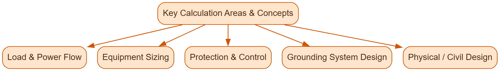
Key Calculation Areas & Concepts
- Load & Power Flow:
- Calculate current (I) for given Apparent Power (S in VA) and Voltage (V):
- 𝐼=𝑆/(√3x𝑉)
- Determine total power demand for sizing transformers and switchgear.
2. Equipment Sizing:
- Transformers: Rated in MVA; selected based on load and voltage levels (e.g., 400kV to 220kV).
- Circuit Breakers (CBs): Rated by voltage and current; selected to interrupt fault currents (e.g., VCB, ACB).
- Busbars & Conductors: Sized for continuous current carrying capacity.
3. Protection & Control:
- Relay Settings: Based on fault levels (short circuit analysis).
- Breaker Failure Schemes: Ensure reliability if primary breaker fails.
4. Grounding System Design:
- Soil resistivity testing.
- Calculate maximum grid potential rise (GPR).
- Calculate Step & Touch Voltages to ensure safety.
5. Physical/Civil Design:
- Clearances: Vertical and horizontal distances for live parts to ground/personnel (based on voltage & pollution levels).
- Site Layout: Equipment spacing, access, drainage (using topography reports).
Electrical substations form the backbone of a reliable power system, enabling safe voltage transformation, controlled power flow, and effective network protection. A sound understanding of substation types, layouts, components, and key design calculations is essential for ensuring system reliability, safety, and operational efficiency. Proper planning, accurate sizing, robust protection schemes, and well-designed grounding and civil layouts collectively ensure that substations operate securely and meet present and future power system demands.