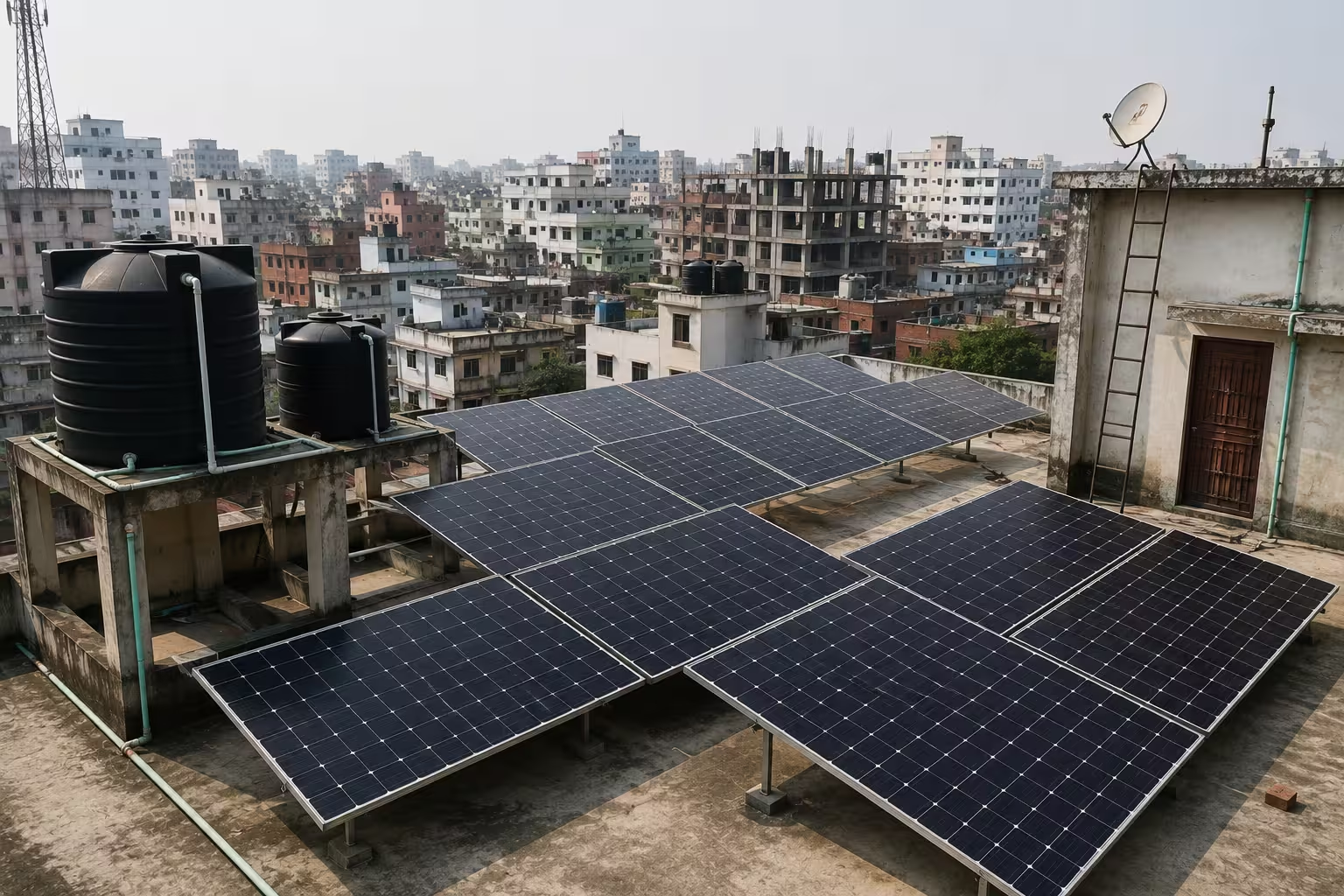
There’s a specific kind of sinking feeling you get when a rooftop solar system in Dhaka is producing 18% less than what was promised on paper, and the client is standing there with the PVsyst report you handed them six months ago. Somewhere between the design table and the roof, a water tank, a neighbour’s third floor extension, or a rusting satellite dish ate into your output — and nobody caught it until the meters told on you.
That’s the whole reason shadow analysis exists. Not as a checkbox in the design process, but as the thing standing between a system that performs and a system that quietly disappoints someone for the next 20 years.
If you’re designing rooftop PV in Bangladesh — Dhaka, Chattogram, Sylhet, wherever — you’re dealing with a specific set of headaches that a generic PVsyst tutorial written for a suburban American rooftop just doesn’t cover. Tight plots, shared walls, water tanks on every second roof, minarets and mobile towers popping up in unpredictable places, and a monsoon sky that behaves nothing like the clear, dry skies most PVsyst tutorials assume. This is a walkthrough built around that reality, not around a textbook rooftop.
Why Shadow Analysis Matters More Than the Brochure Tells You
Here’s something most guides skip: shading loss doesn’t scale in a straight line with shaded area. Shade 10% of an array and you might lose more than 10% of output — sometimes a lot more — because of how PV cells and strings are wired together electrically. A single shaded cell can throttle the current for an entire string, not just the portion under shadow. This is why a PVsyst report can show a shading factor that looks small on the 3D model but a shading loss on the loss diagram that makes you wince.
For rooftop projects packed into a dense city like Dhaka, this matters enormously. You’re rarely dealing with wide-open land where you can just push rows apart until shading disappears. You’re working with a fixed roof, a water tank someone refuses to relocate, and a five-storey building next door that didn’t exist when the original site survey was done. Understanding that shading losses punch above their weight is what pushes a designer to actually run the numbers instead of eyeballing the layout.
If you want the broader physics behind why sun angle and intensity change through the day and across seasons — which directly affects how shadows fall — it’s worth reading up on solar angles and peak sun hours before you even open PVsyst. It makes the shading behaviour in the software click faster.
Near Shading vs. Far Shading — PVsyst Treats Them Completely Differently
PVsyst splits shading into two categories, and mixing them up is one of the most common beginner mistakes.
Far shading is anything distant enough — roughly ten times the size of your PV system away — that it affects the entire array uniformly. Think a hill on the horizon, or a tall building a few streets over in a place like Gulshan or Banani. PVsyst handles this through a horizon profile: a simple curve of height versus azimuth. When the sun dips behind that horizon, the beam component of sunlight just switches off for the whole array at once.
Near shading is the messier, more site-specific stuff — a water tank two feet from your last row, a parapet wall, an adjacent building close enough that its shadow moves across your array differently depending on which row and which module you’re looking at. This needs a proper 3D model, because near shading doesn’t affect the whole system equally. It creeps across specific rows at specific times, and that’s exactly the kind of shading that quietly kills output on Bangladeshi rooftops, where buildings sit shoulder to shoulder.
| Far Shading | Near Shading | |
| Distance | Roughly 10x system size or more | Close to the array |
| Modeling | Horizon profile (height vs. azimuth) | Full 3D scene |
| Effect on array | Uniform, on/off | Partial, varies row by row |
| Common Bangladesh example | Distant hills, tall towers across the street | Water tanks, parapet walls, neighbouring rooftops |
Setting Up Your Project — Do You Even Need a Full 3D Scene?
Not every rooftop needs the full 3D treatment, and knowing when to skip it saves real time.
If your site sits reasonably clear — say, a standalone building in a newer development on the outskirts of Dhaka, or a factory rooftop in an industrial zone with nothing nearby tall enough to matter — a far-shading horizon profile might be all you need. Sketch the horizon, feed it in, and move on.
But most urban rooftops in Bangladesh aren’t that lucky. If there’s a neighbouring building within a few metres, a water tank on the roof itself, a lift overrun, or an antenna cluster, you need the 3D scene. The rule of thumb I use: if you can stand on the roof and something taller than your panel height is within about 15–20 metres, build the model. Don’t guess.
Before building anything, get your site data straight — GPS coordinates, roof orientation, obstacle heights and positions, and ideally a rough sketch or drone photo of the roof. This is also where you decide your system type. For dense city plots, rooftop mounting brings its own shading headaches compared to open ground-mount, mostly because you can’t just relocate the array to dodge a shadow — the roof is the roof.
Building the 3D Shading Scene in PVsyst
This is where PVsyst earns its reputation for being powerful but not exactly friendly to beginners.
Inside your project, head to Near Shadings → Construction/Perspective. From here you build your scene: place your PV field first, using the actual module dimensions and row layout you’re planning, then start adding obstacles — the water tank, the parapet, the neighbouring structure — with real measured heights and positions, not estimates.
If you’ve already got a SketchUp model of the roof (common if an architect or surveyor gave you one), you can import it directly as a .3DS file rather than rebuilding everything from scratch inside PVsyst. This saves a lot of time on complex or irregular roofs, which, frankly, describes most residential and commercial roofs in older parts of Dhaka.
One setting that trips up a lot of beginners: linked vs. unlinked shading scenes. A linked scene ties the shading calculation directly to your system layout, so if you move a row later, the shading updates automatically. Unlinked scenes are static — useful for quick far-shading checks, but dangerous if you forget it’s not updating and keep tweaking your layout without re-running the shading calc. I’ve seen designers submit a report with an unlinked scene that no longer matched the final layout at all. Always double-check which mode you’re in before you trust the output.
Reading the Shading Factor and Loss Diagram
Once the simulation runs, PVsyst gives you a shading factor — the ratio of shaded area to total sensitive array area — and, more usefully, a shading loss percentage buried in the loss diagram.
Here’s the nuance worth understanding: PVsyst actually separates shading losses into two types. Irradiance loss is the straightforward deficit in sunlight hitting the shaded cells. Electrical loss comes from mismatch — when one shaded string drags down the current of the whole group it’s wired with. This second one is why shading losses can look disproportionately painful compared to how much of the array is actually in shadow. If your string design routes a partially shaded row through the same MPPT as an unshaded one, you can end up paying for shade you’d think would be minor.
As a rule of thumb, shading losses sitting above roughly 3–5% are usually worth investigating and possibly redesigning around — though where exactly that line sits depends on your system economics, available roof area, and how much flexibility you actually have on a given site. It’s not a hard PVsyst output or a legal threshold, just a sensible trigger to stop and look closer.
Optimizing Your Layout: Row Spacing, Tilt, and Azimuth
Once you know where the losses are coming from, PVsyst’s Tools → Optimize Tilt & Spacing feature helps you work out the minimum row spacing needed to avoid inter-row shading at your site’s worst-case sun elevation — usually the winter solstice, when the sun sits lowest in the sky.
On a spacious ground-mount project this is easy: increase the pitch until shading disappears. On a Bangladeshi rooftop with a fixed, limited footprint, you’re almost always trading off row spacing against how many kWp you can actually fit. Push rows too far apart and you lose capacity; pack them too tight and you eat shading losses during the low-sun months, typically November through February here.
Tilt and azimuth adjustments help too, though on flat concrete rooftops — the norm across most of urban Bangladesh — you’re usually constrained by structural mounting limits and local wind-loading considerations more than by the software’s ideal angle. It’s worth reading up on how solar angles shift across latitudes if you’re comparing a Dhaka rooftop to a project further south or in a different climate zone — this is also where the distinction between tropical and temperate solar behaviour actually becomes relevant to your spacing decisions, not just a textbook fact.
When Shading Is Unavoidable
Sometimes you simply can’t design your way out of a shadow. The water tank isn’t moving. The neighbour’s building isn’t coming down. In those cases, a few practical fixes:
- Module-level DC optimizers limit the mismatch damage by managing each panel’s output individually rather than letting a whole string get dragged down by one shaded module.
- Microinverters go a step further, converting DC to AC at the module level, so shading on one panel barely touches its neighbours.
- Relocating specific modules away from the worst-affected zone, even if it means a slightly less tidy layout, is often more cost-effective than fighting the shadow with electronics.
- Re-stringing so shaded and unshaded modules aren’t wired into the same series string reduces electrical mismatch loss without adding hardware cost at all.
None of these are exotic — they’re standard tools. The trick is recognizing early, from the loss diagram, that you actually need one of them instead of just accepting the number and moving on.
Validating Your Model on Site
A 3D shading scene is only as good as the measurements that went into it. I’ve seen a parapet wall modeled two feet shorter than it actually was, and the resulting shading report looked clean — right up until the real system underperformed by a margin nobody could explain until someone climbed back up to the roof with a tape measure.
Before you sign off on a design, validate it. A basic tool like a Solar Pathfinder gives you a physical read of the sky obstruction from the array location. For larger or harder-to-access commercial rooftops, a drone survey gets you accurate obstacle heights and positions far faster than manual measurement, and it’s becoming standard practice on bigger IDCOL-linked and industrial rooftop projects in Bangladesh. Either way, treat on-site validation as part of the workflow, not an optional extra you skip when you’re behind schedule.
Common Mistakes Beginners Make
A short list, because these come up constantly:
- Estimating obstacle heights instead of measuring them — a water tank guessed at 1.5m when it’s actually 2.2m throws off the whole scene.
- Forgetting seasonal changes — a tree in leaf blocks far more sun than the same tree bare in winter, and PVsyst lets you account for this if you remember to set it.
- Leaving a shading scene unlinked after changing the layout, so the report no longer reflects reality.
- Ignoring how string and MPPT wiring interacts with shading patterns, which is where a lot of the “surprise” electrical losses come from.
- Treating the shading factor as the whole story, when the loss diagram is where the real answer lives.
None of these are complicated once you know to watch for them. They’re just easy to miss the first few times through a project.
A Quick Note on System Design Beyond Shading
Shadow analysis is one piece of a bigger design puzzle. Whether you’re building an on-grid rooftop system feeding into the national grid or working with a hybrid setup, your shading results feed directly into decisions about inverter sizing, string configuration, and whether a DC or AC-coupled approach makes more sense for the site. Getting the shadow analysis right early saves you from re-doing electrical design work later — it’s genuinely one of the first things worth nailing down, not a late-stage check.
FAQs
What is shadow analysis in solar PV design?
It’s the process of identifying and measuring how nearby obstacles — buildings, trees, water tanks, towers — block sunlight from reaching a PV array at different times of day and year, so the layout can be adjusted to minimize the resulting energy loss.
What’s a good shading loss percentage for a rooftop system?
There’s no fixed number, but shading losses creeping above roughly 3–5% are usually worth a closer look. Whether it’s actually worth redesigning around depends on your available roof space and project economics.
Do I need a full 3D shading model for every rooftop?
Not always. If the site is genuinely clear of nearby obstacles, a simpler far-shading horizon profile can be enough. Once there’s anything close — a water tank, an adjacent building, a parapet — build the 3D scene.
Can PVsyst account for a tree that loses its leaves seasonally?
Yes. You can define obstacles as seasonal or adjust their effective height by month, which matters more than people expect for sites near deciduous trees.
Why does my shading loss look worse than the shaded area suggests it should?
Because shading losses aren’t linear — a small shaded area can trigger a larger electrical mismatch loss if it drags down an entire string’s current. This is the electrical shading component, separate from the straightforward irradiance loss.
Is PVsyst better than SketchUp for shading work, or do I need both?
They usually work together, not against each other. SketchUp is often used to build a detailed 3D roof model, which then gets imported into PVsyst as a .3DS file for the actual shading and energy simulation.